SeminarcenterFull
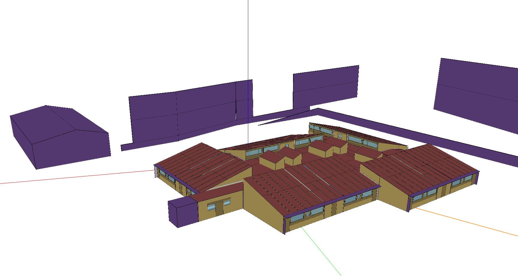
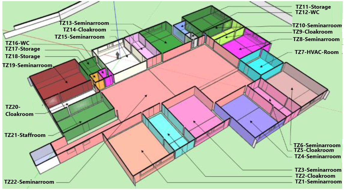
Seminarcenter test site is located in Denmark. It is a one-story building situated at an altitude of 248 meters over sea level, with a total surface area of 1278.94m2 and a total air volume of 3764.95m3. It includes the following 22 conditioned rooms:
1 Large seminar room.
9 Small seminar rooms.
3 Storage rooms.
5 Cloakrooms.
1 Staffroom.
2 Bathrooms.
1 HVAC air handling equipment room.
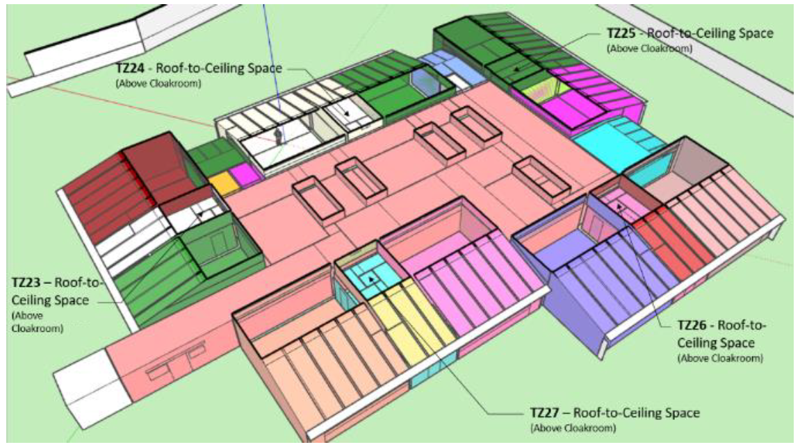
And 5 additional unconditioned areas:
5 Roof-to-ceiling space above Cloakrooms.
Thermal systems
The endpoint thermal distribution setup of Seminarcenter’s HVAC system consists of a series of water convectors deployed in different rooms that operate cooperatively with an Air Handling Unit (AHU) to provide heating to the different spaces. There is no cooling in this building.
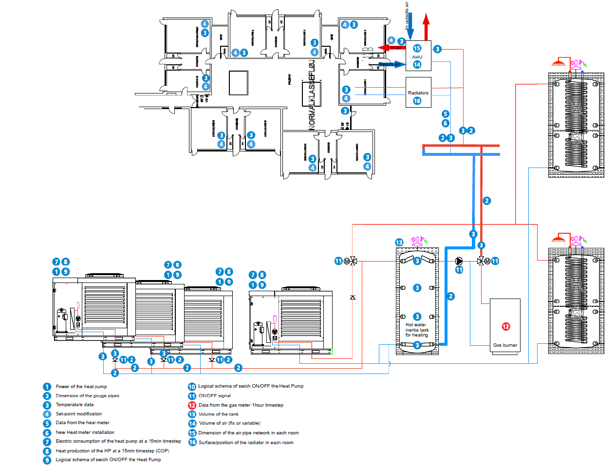
The HVAC supply system allows it to serve the combined demand for heating and domestic hot water on the building. Thus, the HVAC system is composed by six different circuits or loops, one air loop, one domestic hot water loop, four heating water loops that supply heating for all the utilities, including the water convectors, and three heating water loops whose purpose is to supply the previous circuits with heating:
The air loop handles the ventilation requirement and provides conditioned air to the thermal zones.
The buffer tank water loop that delivers heating hot water to the seminar center, including the coil of the AHU and the water convectors installed to increase the space temperature.
In this case there are two main hot water supply loops that provide heating to the buffer tank: one with the Heat Pump Water Heater (HPWH) Group and the other with a gas fired condensing boiler.
Finally, the domestic hot water loop and the Heat Pump Water Heater – Unit 1 loop that supplies both the buffer tank and the domestic hot water with heating.
Air loop for ventilation
The AHU consists of two fan components, one water coil (heating), an air heat recovery system (Air to air Heat exchanger) and an outdoor air system (fresh air). The supply and extract fans are fixed as constant volume with a total efficiency of 0.7. The water coil is the demand side of the buffer tank water loop (heating). Finally, the outdoor air system provides outdoor air for ventilation. In this case, to increase the AHU efficiency, the system, as currently implemented, recirculates the air and recovers the heat from the exhaust air at a fixed efficiency of 0.75
Heating loop
The integrated system is based on an air to water HP Thermal Group (heat pumps 1 to 4) that supplies heating to the buffer tank loop, and thus to the AHU and the water convectors in the building. If the HP Group cannot handle the thermal zones heating demand during certain peak hours, the boiler loop acts as an auxiliary system to supply the required heating water into the system.
Electrical systems
The site incorporates a 12 kW photovoltaic installation.
Controllable components
Fan coil control
The room temperature setpoints can be controlled. On the contrary to other buildings in the large seminar room, and ideal room temperature control with thermostat is implemented (no hysteresis control).
Heat pump control
The user has the possibility to control the water supply temperature and the on/off mode of each individual pump.
AHU control
The user has the possibility to control the AHU coil temperature and the AHU air temperature setpoints.
Buffer Tank control
The user has the possibility to control the buffer tank temperature setpoint.
Simulation inputs
For more detail, please check the documentation The Seminarcenter environment or the source code energym.envs.seminarcenter.seminarcenter.Seminarcenter.
Variable Name |
Type |
Lower Bound |
Upper Bound |
# States |
Description |
|---|---|---|---|---|---|
Bd_onoff_HP1_sp |
discrete |
2 |
Heat pump 1 on/off setpoint. |
||
Bd_onoff_HP2_sp |
discrete |
2 |
Heat pump 2 on/off setpoint. |
||
Bd_onoff_HP3_sp |
discrete |
2 |
Heat pump 3 on/off setpoint. |
||
Bd_onoff_HP4_sp |
discrete |
2 |
Heat pump 4 on/off setpoint. |
||
Bd_T_HP1_sp |
scalar |
30 |
65 |
Heat pump 1 temperature setpoint (°C). |
|
Bd_T_HP2_sp |
scalar |
30 |
65 |
Heat pump 2 temperature setpoint (°C). |
|
Bd_T_HP3_sp |
scalar |
30 |
65 |
Heat pump 3 temperature setpoint (°C). |
|
Bd_T_HP4_sp |
scalar |
30 |
65 |
Heat pump 4 temperature setpoint (°C). |
|
Bd_T_AHU_coil_sp |
scalar |
15 |
40 |
AHU temperature setpoint (°C). |
|
Bd_T_buffer_sp |
scalar |
15 |
70 |
Buffer tank temperature setpoint (°C). |
|
Bd_T_mixer_sp |
scalar |
20 |
60 |
Mixer temperature setpoint (°C). |
|
Bd_T_Boiler_sp |
scalar |
20 |
80 |
Gas boiler temperature setpoint (°C). |
|
Bd_T_HVAC_sp |
scalar |
10 |
26 |
HVAC temperature setpoint (°C). |
|
Z01_T_Thermostat_sp |
scalar |
16 |
26 |
Zone 1 thermostat setpoint (°C). |
|
Z02_T_Thermostat_sp |
scalar |
16 |
26 |
Zone 2 thermostat setpoint (°C). |
|
Z03_T_Thermostat_sp |
scalar |
16 |
26 |
Zone 3 thermostat setpoint (°C). |
|
Z04_T_Thermostat_sp |
scalar |
16 |
26 |
Zone 4 thermostat setpoint (°C). |
|
Z05_T_Thermostat_sp |
scalar |
16 |
26 |
Zone 5 thermostat setpoint (°C). |
|
Z06_T_Thermostat_sp |
scalar |
16 |
26 |
Zone 6 thermostat setpoint (°C). |
|
Z08_T_Thermostat_sp |
scalar |
16 |
26 |
Zone 8 thermostat setpoint (°C). |
|
Z09_T_Thermostat_sp |
scalar |
16 |
26 |
Zone 9 thermostat setpoint (°C). |
|
Z10_T_Thermostat_sp |
scalar |
16 |
26 |
Zone 10 thermostat setpoint (°C). |
|
Z11_T_Thermostat_sp |
scalar |
16 |
26 |
Zone 11 thermostat setpoint (°C). |
|
Z13_T_Thermostat_sp |
scalar |
16 |
26 |
Zone 13 thermostat setpoint (°C). |
|
Z14_T_Thermostat_sp |
scalar |
16 |
26 |
Zone 14 thermostat setpoint (°C). |
|
Z15_T_Thermostat_sp |
scalar |
16 |
26 |
Zone 15 thermostat setpoint (°C). |
|
Z18_T_Thermostat_sp |
scalar |
16 |
26 |
Zone 18 thermostat setpoint (°C). |
|
Z19_T_Thermostat_sp |
scalar |
16 |
26 |
Zone 19 thermostat setpoint (°C). |
|
Z20_T_Thermostat_sp |
scalar |
16 |
26 |
Zone 20 thermostat setpoint (°C). |
|
Z21_T_Thermostat_sp |
scalar |
16 |
26 |
Zone 21 thermostat setpoint (°C). |
|
Z22_T_Thermostat_sp |
scalar |
16 |
26 |
Zone 22 thermostat setpoint (°C). |
Simulation outputs
Variable Name |
Type |
Lower Bound |
Upper Bound |
# States |
Description |
|---|---|---|---|---|---|
Bd_Pw_All |
scalar |
0 |
100000.0 |
Building power consumption (W). |
|
Bd_Pw_prod |
scalar |
0 |
10000.0 |
PV power production (W). |
|
Bd_Pw_boiler |
scalar |
0 |
300000.0 |
Gas boiler power consumption (W). |
|
Ext_Irr |
scalar |
0 |
1000 |
Direct normal radiation (W/m2). |
|
Ext_RH |
scalar |
0 |
100 |
Outdoor relative humidity (%RH). |
|
Ext_T |
scalar |
-15 |
40 |
Outdoor temperature (°C). |
|
Ext_P |
scalar |
80000 |
130000 |
Outdoor air pressure (Pa). |
|
Fa_Pw_All |
scalar |
0 |
100000.0 |
Total power consumption (W). |
|
Fa_Pw_HVAC |
scalar |
0 |
100000.0 |
HVAC power consumption (W). |
|
Fa_Pw_Pur |
scalar |
0 |
100000.0 |
Purchased power (W). |
|
Z01_RH |
scalar |
0 |
100 |
Zone 1 relative humidity (%RH). |
|
Z01_T |
scalar |
10 |
40 |
Zone 1 temperature (°C). |
|
Z01_T_Thermostat_sp_out |
scalar |
16 |
26 |
Zone 1 thermostat setpoint (°C). |
|
Z02_RH |
scalar |
0 |
100 |
Zone 2 relative humidity (%RH). |
|
Z02_T |
scalar |
10 |
40 |
Zone 2 temperature (°C). |
|
Z02_T_Thermostat_sp_out |
scalar |
16 |
26 |
Zone 2 thermostat setpoint (°C). |
|
Z03_RH |
scalar |
0 |
100 |
Zone 3 relative humidity (%RH). |
|
Z03_T |
scalar |
10 |
40 |
Zone 3 temperature (°C). |
|
Z03_T_Thermostat_sp_out |
scalar |
16 |
26 |
Zone 3 thermostat setpoint (°C). |
|
Z04_RH |
scalar |
0 |
100 |
Zone 4 relative humidity (%RH). |
|
Z04_T |
scalar |
10 |
40 |
Zone 4 temperature (°C). |
|
Z04_T_Thermostat_sp_out |
scalar |
16 |
26 |
Zone 4 thermostat setpoint (°C). |
|
Z05_RH |
scalar |
0 |
100 |
Zone 5 relative humidity (%RH). |
|
Z05_T |
scalar |
10 |
40 |
Zone 5 temperature (°C). |
|
Z05_T_Thermostat_sp_out |
scalar |
16 |
26 |
Zone 5 thermostat setpoint (°C). |
|
Z06_RH |
scalar |
0 |
100 |
Zone 6 relative humidity (%RH). |
|
Z06_T |
scalar |
10 |
40 |
Zone 6 temperature (°C). |
|
Z06_T_Thermostat_sp_out |
scalar |
16 |
26 |
Zone 6 thermostat setpoint (°C). |
|
Z08_RH |
scalar |
0 |
100 |
Zone 8 relative humidity (%RH). |
|
Z08_T |
scalar |
10 |
40 |
Zone 8 temperature (°C). |
|
Z08_T_Thermostat_sp_out |
scalar |
16 |
26 |
Zone 8 thermostat setpoint (°C). |
|
Z09_RH |
scalar |
0 |
100 |
Zone 9 relative humidity (%RH). |
|
Z09_T |
scalar |
10 |
40 |
Zone 9 temperature (°C). |
|
Z09_T_Thermostat_sp_out |
scalar |
16 |
26 |
Zone 9 thermostat setpoint (°C). |
|
Z10_RH |
scalar |
0 |
100 |
Zone 10 relative humidity (%RH). |
|
Z10_T |
scalar |
10 |
40 |
Zone 10 temperature (°C). |
|
Z10_T_Thermostat_sp_out |
scalar |
16 |
26 |
Zone 10 thermostat setpoint (°C). |
|
Z11_RH |
scalar |
0 |
100 |
Zone 11 relative humidity (%RH). |
|
Z11_T |
scalar |
10 |
40 |
Zone 11 temperature (°C). |
|
Z11_T_Thermostat_sp_out |
scalar |
16 |
26 |
Zone 11 thermostat setpoint (°C). |
|
Z13_RH |
scalar |
0 |
100 |
Zone 12 relative humidity (%RH). |
|
Z13_T |
scalar |
10 |
40 |
Zone 13 temperature (°C). |
|
Z13_T_Thermostat_sp_out |
scalar |
16 |
26 |
Zone 13 thermostat setpoint (°C). |
|
Z14_RH |
scalar |
0 |
100 |
Zone 14 relative humidity (%RH). |
|
Z14_T |
scalar |
10 |
40 |
Zone 14 temperature (°C). |
|
Z14_T_Thermostat_sp_out |
scalar |
16 |
26 |
Zone 14 thermostat setpoint (°C). |
|
Z15_RH |
scalar |
0 |
100 |
Zone 15 relative humidity (%RH). |
|
Z15_T |
scalar |
10 |
40 |
Zone 15 temperature (°C). |
|
Z15_T_Thermostat_sp_out |
scalar |
16 |
26 |
Zone 15 thermostat setpoint (°C). |
|
Z18_RH |
scalar |
0 |
100 |
Zone 18 relative humidity (%RH). |
|
Z18_T |
scalar |
10 |
40 |
Zone 18 temperature (°C). |
|
Z18_T_Thermostat_sp_out |
scalar |
16 |
26 |
Zone 18 thermostat setpoint (°C). |
|
Z19_RH |
scalar |
0 |
100 |
Zone 19 relative humidity (%RH). |
|
Z19_T |
scalar |
10 |
40 |
Zone 19 temperature (°C). |
|
Z19_T_Thermostat_sp_out |
scalar |
16 |
26 |
Zone 19 thermostat setpoint (°C). |
|
Z20_RH |
scalar |
0 |
100 |
Zone 20 relative humidity (%RH). |
|
Z20_T |
scalar |
10 |
40 |
Zone 20 temperature (°C). |
|
Z20_T_Thermostat_sp_out |
scalar |
16 |
26 |
Zone 20 thermostat setpoint (°C). |
|
Z21_RH |
scalar |
0 |
100 |
Zone 21 relative humidity (%RH). |
|
Z21_T |
scalar |
10 |
40 |
Zone 21 temperature (°C). |
|
Z21_T_Thermostat_sp_out |
scalar |
16 |
26 |
Zone 21 thermostat setpoint (°C). |
|
Z22_RH |
scalar |
0 |
100 |
Zone 22 relative humidity (%RH). |
|
Z22_T |
scalar |
10 |
40 |
Zone 22 temperature (°C). |
|
Z22_T_Thermostat_sp_out |
scalar |
16 |
26 |
Zone 22 thermostat setpoint (°C). |
|
Bd_CO2 |
scalar |
0 |
10 |
Building CO2 emission. |
Weather files
The available weather files for this model have the following specifiers:
DNK_SD_BillundDNK_MJ_Horsens1(Default)DNK_MJ_Horsens2(Evaluation file)DNK_MJ_Isenvad1DNK_MJ_Isenvad2DNK_MJ_Karup1DNK_MJ_Karup2DNK_MJ_LyngvigDNK_MJ_Mejrup1DNK_MJ_Mejrup2DNK_MJ_OdumDNK_MJ_Silstrup
Evaluation scenario
The evaluation scenario for the SeminarcenterFull-v0 model consists of a control from January to May with the objective of minimizing the CO2 emission, while keeping the zone temperatures between 21 and 24°C. For this goal, the tracked KPIs are the average CO2 emissions, and the average temperature deviation and total temperature violations with respect to the interval [21, 24].
Notebook example
Here is a notebook example: