MixedUse
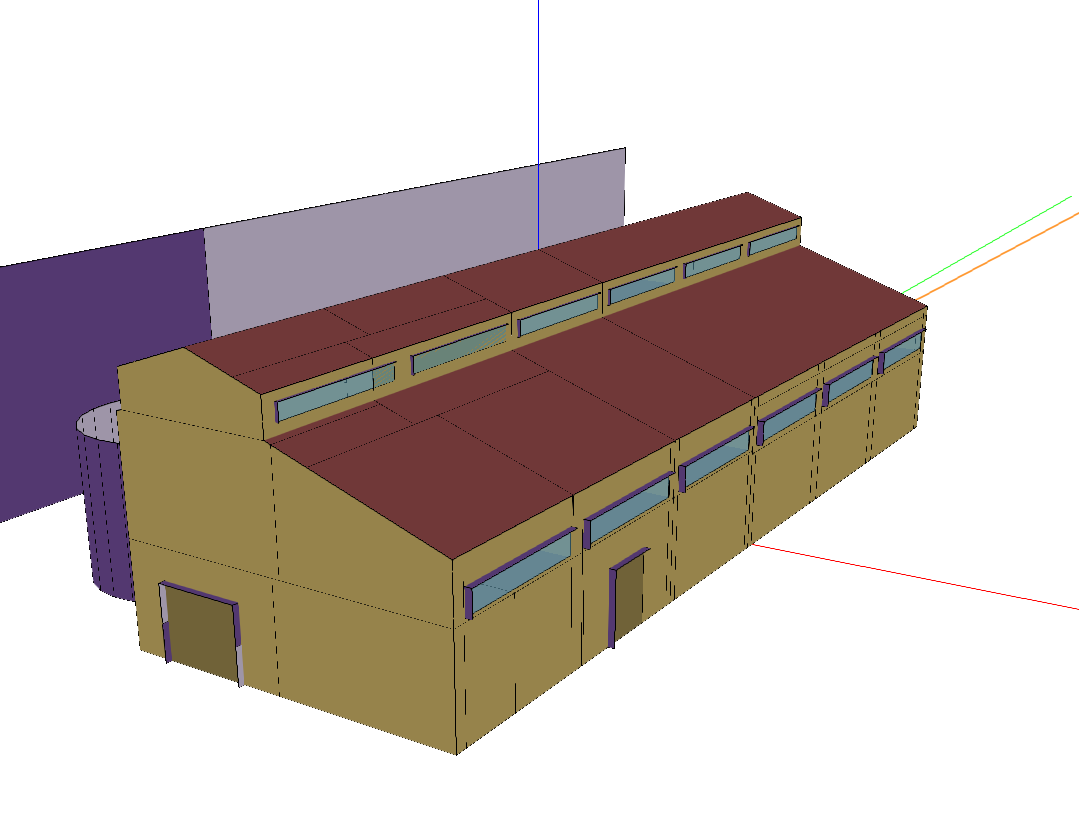
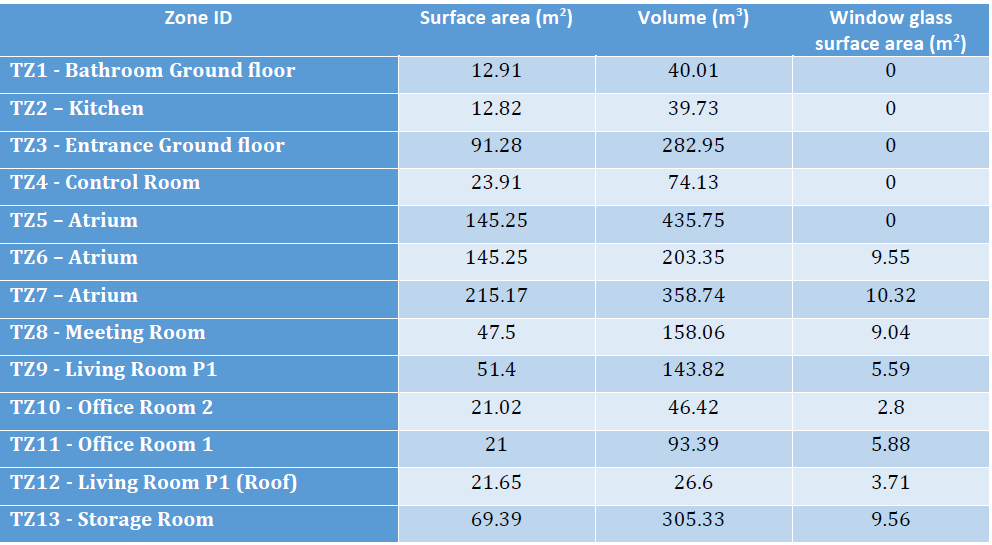
The MixedUse building is located in Greece. It is situated at an altitude of 10 meters over sea level, and has a total surface area of 566.38m2 and a total air volume of 2208.27m3.
Thermal systems
The HVAC system installed for the MixedUse building consists of two Air Handling Units (AHU), one dedicated exclusively to thermal zones 5, 6 and 7 and a second one serving to the remaining thermal zones. Both devices work in conjunction with variable refrigerant volume indoor units to air-condition interior spaces.
The first AHU system dedicated to TZ-5, 6 and 7 is composed of an air loop, an AHU that includes water coils and two supply water loops; one with a Heat Pump Water Heater (HPWH) and the other with a chiller. The second AHU system serving the entire facility consists of an air loop with an AHU that has direct expansion “DX” coils. In addition, the zones that are affected under this system have variable refrigerant flow (VRF) terminal units as part of the air-conditioning system.
Electrical systems
The site incorporates a 48 kW photovoltaic installation. The surface area of the PV panels is 475 m2.
Controllable components
Fan coil control
The room temperature setpoints can be controlled. A low-level hysteresis control loop is implemented to ensure that the room temperature stays close to the setpoints.
AHU control
Both AHUs, the one for the zones 5,6,7, (called AHU1) and the one for the rest of the building (called AHU2) can be controlled. Control variables for AHU1 are the air flow rate of the ventilation system, and the setpoint temperature of the heated or cooled water (air to water heatpump water setpoint, or chilled water setpoint). Control variables for AHU2 are the air flow rate of the ventilation system, and the setpoint temperature of air flow.
Simulation inputs
For more detail, please check the documentation The MixedUse environment or the source code energym.envs.mixeduse.mixeduse.MixedUse.
Variable Name |
Type |
Lower Bound |
Upper Bound |
# States |
Description |
|---|---|---|---|---|---|
Z02_T_Thermostat_sp |
scalar |
16 |
26 |
Zone 2 thermostat setpoint (°C). |
|
Z03_T_Thermostat_sp |
scalar |
16 |
26 |
Zone 3 thermostat setpoint (°C). |
|
Z04_T_Thermostat_sp |
scalar |
16 |
26 |
Zone 4 thermostat setpoint (°C). |
|
Z05_T_Thermostat_sp |
scalar |
16 |
26 |
Zone 5 thermostat setpoint (°C). |
|
Z08_T_Thermostat_sp |
scalar |
16 |
26 |
Zone 8 thermostat setpoint (°C). |
|
Z09_T_Thermostat_sp |
scalar |
16 |
26 |
Zone 9 thermostat setpoint (°C). |
|
Z10_T_Thermostat_sp |
scalar |
16 |
26 |
Zone 10 thermostat setpoint (°C). |
|
Z11_T_Thermostat_sp |
scalar |
16 |
26 |
Zone 11 thermostat setpoint (°C). |
|
Bd_T_AHU2_sp |
scalar |
10 |
30 |
AHU 2 temperature setpoint (°C). |
|
Bd_Fl_AHU2_sp |
scalar |
0 |
1 |
AHU 2 flow rate setpoint. |
|
Bd_T_AHU1_sp |
scalar |
10 |
30 |
AHU 1 temperature setpoint (°C). |
|
Bd_Fl_AHU1_sp |
scalar |
0 |
1 |
AHU1 flow rate setpoint. |
Simulation outputs
Variable Name |
Type |
Lower Bound |
Upper Bound |
# States |
Description |
|---|---|---|---|---|---|
Bd_Pw_All |
scalar |
0 |
10000.0 |
Building power consumption (W). |
|
Bd_Pw_chiller |
scalar |
0 |
30000.0 |
Chiller power consumption (W). |
|
Bd_Pw_coil |
scalar |
0 |
15000.0 |
Heating coil power consumption (W). |
|
Bd_Pw_cooling_AHU2 |
scalar |
0 |
10000.0 |
AHU 2 cooling power (W). |
|
Bd_Pw_cooling_HP |
scalar |
0 |
30000.0 |
Heat pump cooling power (W). |
|
Bd_Pw_heating_HP |
scalar |
0 |
30000.0 |
Heat pump heating power (W). |
|
Bd_T_AHU1 |
scalar |
10 |
30 |
AHU 1 temperature (°C). |
|
Bd_T_AHU2 |
scalar |
10 |
30 |
AHU 2 temperature (°C). |
|
Ext_Irr |
scalar |
0 |
1000 |
Direct normal radiation (W/m2). |
|
Ext_P |
scalar |
80000.0 |
130000.0 |
Outdoor air pressure (Pa). |
|
Ext_RH |
scalar |
0 |
100 |
Outdoor realtive humidity (%RH). |
|
Ext_T |
scalar |
-10 |
40 |
Outdoor temperature (°C). |
|
Fa_Pw_All |
scalar |
0 |
50000.0 |
Total power consumtion (W). |
|
Fa_Pw_HVAC |
scalar |
0 |
50000.0 |
HVAC power consumption (W). |
|
Z02_Fl_Fan |
scalar |
0 |
1 |
Zone 2 fan flow rate. |
|
Z02_RH |
scalar |
0 |
100 |
Zone 2 relative humidity (%RH). |
|
Z02_T |
scalar |
10 |
40 |
Zone 2 temperature (°C). |
|
Z02_T_Thermostat_sp_out |
scalar |
16 |
26 |
Zone 2 thermostat setpoint (°C). |
|
Z03_Fl_Fan |
scalar |
0 |
1 |
Zone 3 fan flow rate. |
|
Z03_RH |
scalar |
0 |
100 |
Zone 3 relative humidity (%RH). |
|
Z03_T |
scalar |
10 |
40 |
Zone 3 temperature (°C). |
|
Z03_T_Thermostat_sp_out |
scalar |
16 |
26 |
Zone 3 thermostat setpoint (°C). |
|
Z04_Fl_Fan |
scalar |
0 |
1 |
Zone 4 fan flow rate. |
|
Z04_RH |
scalar |
0 |
100 |
Zone 4 relative humidity (%RH). |
|
Z04_T |
scalar |
10 |
40 |
Zone 4 temperature (°C). |
|
Z04_T_Thermostat_sp_out |
scalar |
16 |
26 |
Zone 4 thermostat setpoint (°C). |
|
Z05_RH |
scalar |
0 |
100 |
Zone 5 relative humidity (%RH). |
|
Z05_T |
scalar |
10 |
40 |
Zone 5 temperature (°C). |
|
Z05_T_Thermostat_sp_out |
scalar |
16 |
26 |
Zone 5 thermostat setpoint (°C). |
|
Z08_Fl_Fan |
scalar |
0 |
1 |
Zone 8 fan flow rate. |
|
Z08_RH |
scalar |
0 |
100 |
Zone 8 relative humidity (%RH). |
|
Z08_T |
scalar |
10 |
40 |
Zone 8 temperature (°C). |
|
Z08_T_Thermostat_sp_out |
scalar |
16 |
26 |
Zone 8 thermostat setpoint (°C). |
|
Z09_Fl_Fan |
scalar |
0 |
1 |
Zone 9 fan flow rate. |
|
Z09_RH |
scalar |
0 |
100 |
Zone 9 relative humidity (%RH). |
|
Z09_T |
scalar |
10 |
40 |
Zone 9 temperature (°C). |
|
Z09_T_Thermostat_sp_out |
scalar |
16 |
26 |
Zone 9 thermostat setpoint (°C). |
|
Z10_Fl_Fan |
scalar |
0 |
1 |
Zone 10 fan flow rate. |
|
Z10_RH |
scalar |
0 |
100 |
Zone 10 relative humidity (%RH). |
|
Z10_T |
scalar |
10 |
40 |
Zone 10 temperature (°C). |
|
Z10_T_Thermostat_sp_out |
scalar |
16 |
26 |
Zone 10 thermostat setpoint (°C). |
|
Z11_Fl_Fan |
scalar |
0 |
1 |
Zone 11 fan flow rate. |
|
Z11_RH |
scalar |
0 |
100 |
Zone 11 relative humidity (%RH). |
|
Z11_T |
scalar |
10 |
40 |
Zone 11 temperature (°C). |
|
Z11_T_Thermostat_sp_out |
scalar |
16 |
26 |
Zone 11 thermostat setpoint (°C). |
Weather files
The available weather files for this model have the following specifiers:
GRC_A_Athens(Default)GRC_TC_Lamia1(Evaluation file)GRC_TC_Lamia2GRC_TC_LarisaAP1GRC_TC_LarisaAP2GRC_TC_NeaAnchialosAP1GRC_TC_NeaAnchialosAP2GRC_TC_SkiathosAPGRC_TC_TanagraAP1GRC_TC_TanagraAP2GRC_TC_Trikala
Evaluation scenario
The evaluation scenario for the MixedUseFanFCU-v0 model consists of a full year control with the objective of minimizing the power demand, while keeping the zone temperatures between 19 and 24°C. For this goal, the tracked KPIs are the average power demand on the facility level, and the average temperature deviation and total temperature violations with respect to the interval [19, 24].
Notebook example
Here is a notebook example: