Offices
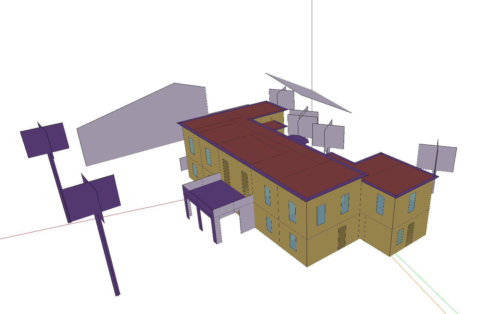
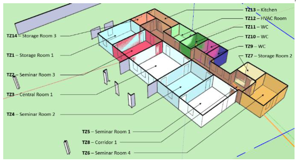
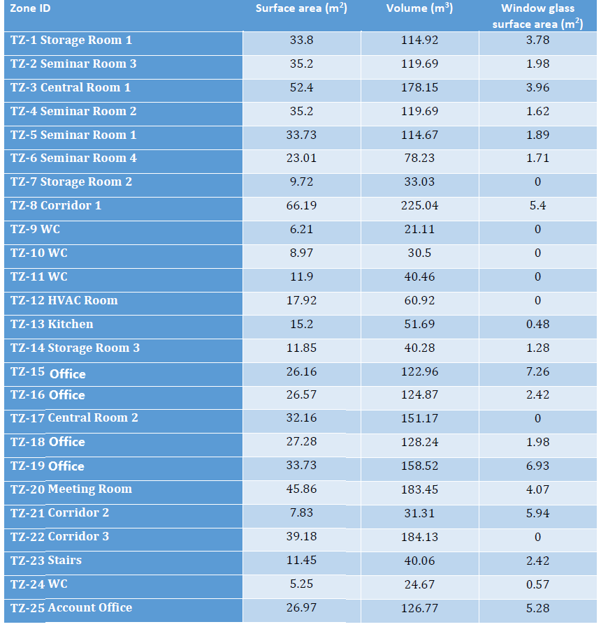
Offices building is located in Greece. It is situated at an altitude of 4 meters over sea level, and has a total surface area of 643.73m2 and a total air volume of 2504.54m3. It includes the following 25 conditioned rooms:
3 Storage Rooms.
4 Seminar Rooms.
2 Central Rooms (Lobbies).
3 Corridors.
1 Staircase
4 WC (Bathrooms).
1 Kitchen.
5 Office Spaces.
1 Meeting Room.
1 HVAC air handling equipment room.

Thermal systems
The systems installed consist of a series of water to air fan coil units, deployed in different conditioned spaces of the building. This test site does not include an Air Handling Unit (AHU) of any kind, or any other forced ventilation/air climatization system. The installed fan coil units are supplied by a two-pipe water distribution system connected to a valve setup that can either send hot water from an oil boiler for heating demands, or deliver chilled water from an electrical air to water chiller, but not both.
Electrical systems
The site incorporates a 10 kW photovoltaic installation.
Controllable components
Fan coil control
The room temperature setpoints can be controlled. A low-level hysteresis control loop is implemented to ensure that the room temperature stays close to the setpoints. Notice that not all thermal zones are controllable (corridors, WC, Stairs, HVAC Room, Storage rooms and Kitchen have no thermostat control)
Chiller/Boiler control
The user can decide whether to heat up or cool down the building, by putting the boiler on/off and the chiller on/off. It is forbiden to use both heating and cooling at the same time.
Simulation inputs
For more detail, please check the documentation The Offices environment or the source code in energym.envs.offices.offices.Offices.
Variable Name |
Type |
Lower Bound |
Upper Bound |
# States |
Description |
|---|---|---|---|---|---|
Bd_Cooling_onoff_sp |
discrete |
2 |
Cooling availability on/off setpoint. |
||
Bd_Heating_onoff_sp |
discrete |
2 |
Heating availability on/off setpoint. |
||
Z01_T_Thermostat_sp |
scalar |
16 |
26 |
Zone 1 thermostat setpoint (°C). |
|
Z02_T_Thermostat_sp |
scalar |
16 |
26 |
Zone 2 thermostat setpoint (°C). |
|
Z03_T_Thermostat_sp |
scalar |
16 |
26 |
Zone 3 thermostat setpoint (°C). |
|
Z04_T_Thermostat_sp |
scalar |
16 |
26 |
Zone 4 thermostat setpoint (°C). |
|
Z05_T_Thermostat_sp |
scalar |
16 |
26 |
Zone 5 thermostat setpoint (°C). |
|
Z06_T_Thermostat_sp |
scalar |
16 |
26 |
Zone 6 thermostat setpoint (°C). |
|
Z07_T_Thermostat_sp |
scalar |
16 |
26 |
Zone 7 thermostat setpoint (°C). |
|
Z15_T_Thermostat_sp |
scalar |
16 |
26 |
Zone 15 thermostat setpoint (°C). |
|
Z16_T_Thermostat_sp |
scalar |
16 |
26 |
Zone 16 thermostat setpoint (°C). |
|
Z17_T_Thermostat_sp |
scalar |
16 |
26 |
Zone 17 thermostat setpoint (°C). |
|
Z18_T_Thermostat_sp |
scalar |
16 |
26 |
Zone 18 thermostat setpoint (°C). |
|
Z19_T_Thermostat_sp |
scalar |
16 |
26 |
Zone 19 thermostat setpoint (°C). |
|
Z20_T_Thermostat_sp |
scalar |
16 |
26 |
Zone 20 thermostat setpoint (°C). |
|
Z25_T_Thermostat_sp |
scalar |
16 |
26 |
Zone 25 thermostat setpoint (°C). |
Simulation outputs
Variable Name |
Type |
Lower Bound |
Upper Bound |
# States |
Description |
|---|---|---|---|---|---|
Bd_Pw_All |
scalar |
0 |
5000 |
Building power consumption (W). |
|
Ext_Irr |
scalar |
0 |
1000 |
Direct normal radiation (W/m2). |
|
Ext_RH |
scalar |
0 |
100 |
Outdoor relative humidity (%RH). |
|
Ext_T |
scalar |
-10 |
40 |
Outdoor temperature (°C). |
|
Fa_Pw_All |
scalar |
0 |
10000.0 |
Total power consumption (W). |
|
Fa_Pw_HVAC |
scalar |
0 |
10000.0 |
HVAC power consumption (W). |
|
Fa_Pw_PV |
scalar |
0 |
2000.0 |
PV power production (W). |
|
Z01_Fl_Fan_sp_out |
scalar |
0 |
1 |
Zone 1 fan flow setpoint. |
|
Z01_T |
scalar |
10 |
40 |
Zone 1 temperature (°C). |
|
Z01_T_Thermostat_sp_out |
scalar |
16 |
26 |
Zone 1 thermostat setpoint (°C). |
|
Z02_Fl_Fan_sp_out |
scalar |
0 |
1 |
Zone 2 fan flow setpoint. |
|
Z02_T |
scalar |
10 |
40 |
Zone 2 temperature (°C). |
|
Z02_T_Thermostat_sp_out |
scalar |
16 |
26 |
Zone 2 thermostat setpoint (°C). |
|
Z03_Fl_Fan_sp_out |
scalar |
0 |
1 |
Zone 3 fan flow setpoint. |
|
Z03_Fl_Fan1_sp_out |
scalar |
0 |
1 |
Zone 3 fan 1 flow setpoint. |
|
Z03_T |
scalar |
10 |
40 |
Zone 3 temperature (°C). |
|
Z03_T_Thermostat_sp_out |
scalar |
16 |
26 |
Zone 3 thermostat setpoint (°C). |
|
Z04_Fl_Fan_sp_out |
scalar |
0 |
1 |
Zone 4 fan flow setpoint. |
|
Z04_T |
scalar |
10 |
40 |
Zone 4 temperature (°C). |
|
Z04_T_Thermostat_sp_out |
scalar |
16 |
26 |
Zone 4 thermostat setpoint (°C). |
|
Z05_Fl_Fan_sp_out |
scalar |
0 |
1 |
Zone 5 fan flow setpoint. |
|
Z05_T |
scalar |
10 |
40 |
Zone 5 temperature (°C). |
|
Z05_T_Thermostat_sp_out |
scalar |
16 |
26 |
Zone 5 thermostat setpoint (°C). |
|
Z06_Fl_Fan_sp_out |
scalar |
0 |
1 |
Zone 6 fan flow setpoint. |
|
Z06_T |
scalar |
10 |
40 |
Zone 6 temperature (°C). |
|
Z06_T_Thermostat_sp_out |
scalar |
16 |
26 |
Zone 6 thermostat setpoint (°C). |
|
Z07_Fl_Fan_sp_out |
scalar |
0 |
1 |
Zone 7 fan flow setpoint. |
|
Z07_T |
scalar |
10 |
40 |
Zone 7 temperature (°C). |
|
Z07_T_Thermostat_sp_out |
scalar |
16 |
26 |
Zone 7 thermostat setpoint (°C). |
|
Z15_Fl_Fan_sp_out |
scalar |
0 |
1 |
Zone 15 fan flow setpoint. |
|
Z15_T |
scalar |
10 |
40 |
Zone 15 temperature (°C). |
|
Z15_T_Thermostat_sp_out |
scalar |
16 |
26 |
Zone 15 thermostat setpoint (°C). |
|
Z16_Fl_Fan_sp_out |
scalar |
0 |
1 |
Zone 16 fan flow setpoint. |
|
Z16_T |
scalar |
10 |
40 |
Zone 16 temperature (°C). |
|
Z16_T_Thermostat_sp_out |
scalar |
16 |
26 |
Zone 16 thermostat setpoint (°C). |
|
Z17_Fl_Fan_sp_out |
scalar |
0 |
1 |
Zone 17 fan flow setpoint. |
|
Z17_Fl_Fan1_sp_out |
scalar |
0 |
1 |
Zone 17 fan 1 flow setpoint. |
|
Z17_T |
scalar |
10 |
40 |
Zone 17 temperature (°C). |
|
Z17_T_Thermostat_sp_out |
scalar |
16 |
26 |
Zone 17 thermostat setpoint (°C). |
|
Z18_Fl_Fan_sp_out |
scalar |
0 |
1 |
Zone 18 fan flow setpoint. |
|
Z18_T |
scalar |
10 |
40 |
Zone 18 temperature (°C). |
|
Z18_T_Thermostat_sp_out |
scalar |
16 |
26 |
Zone 18 thermostat setpoint (°C). |
|
Z19_Fl_Fan_sp_out |
scalar |
0 |
1 |
Zone 19 fan flow setpoint. |
|
Z19_Fl_Fan1_sp_out |
scalar |
0 |
1 |
Zone 19 fan 1 flow setpoint. |
|
Z19_T |
scalar |
10 |
40 |
Zone 19 temperature (°C). |
|
Z19_T_Thermostat_sp_out |
scalar |
16 |
26 |
Zone 19 thermostat setpoint (°C). |
|
Z20_Fl_Fan_sp_out |
scalar |
0 |
1 |
Zone 20 fan flow setpoint. |
|
Z20_Fl_Fan1_sp_out |
scalar |
0 |
1 |
Zone 20 fan 1 flow setpoint. |
|
Z20_T |
scalar |
10 |
40 |
Zone 20 temperature (°C). |
|
Z20_T_Thermostat_sp_out |
scalar |
16 |
26 |
Zone 20 thermostat setpoint (°C). |
|
Z25_Fl_Fan_sp_out |
scalar |
0 |
1 |
Zone 25 fan flow setpoint. |
|
Z25_Fl_Fan1_sp_out |
scalar |
0 |
1 |
Zone 25 fan 1 flow setpoint. |
|
Z25_T |
scalar |
10 |
40 |
Zone 25 temperature (°C). |
|
Z25_T_Thermostat_sp_out |
scalar |
16 |
26 |
Zone 25 thermostat setpoint (°C). |
Weather files
The available weather files for this model have the following specifiers:
GRC_A_Athens(Default)GRC_TC_Lamia1(Evaluation file)GRC_TC_Lamia2GRC_TC_LarisaAP1GRC_TC_LarisaAP2GRC_TC_NeaAnchialosAP1GRC_TC_NeaAnchialosAP2GRC_TC_SkiathosAPGRC_TC_TanagraAP1GRC_TC_TanagraAP2GRC_TC_Trikala
Evaluation scenario
The evaluation scenario for the OfficesThermostat-v0 model consists of a full year control with the objective of minimizing the power demand, while keeping the zone temperatures between 19 and 24°C. For this goal, the tracked KPIs are the average power demand on the facility level, and the average temperature deviation and total temperature violations with respect to the interval [19, 24].
Notebook example
Here is a notebook example: